FBCad Robotic Application Example
![]()
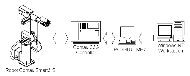
In this section the proposed control system design framework is applied to the design, and implementation, of a mission for an industrial robot. First, the experimental environment is described. The controlled robot is a SMART-3S industrial manipulator, which is a 6 degree of freedom robot manufactured by COMAU. The manipulator is equipped with an open version of the COMAU C3G-9000 controller, that is linked to a PC, with an Intel 486 50 MHz micro-processor. In particular, the C3G controller is linked to the AT bus of the PC, through a VME-AT bus-to-bus communicator adapter. The PC can read the controller internal variables (e.g. joints positions), and overwrite them every 10 ms. Moreover, a PC with a Pentium 166 MHz micro-processor, running Windows NT 4.0, is used acting as a CAD station, where FBCad is installed, and the control system is designed, simulated and on which the executable control code for the 486 PC is generated. The described experimental environment is sketched in Fig. 1 [FERMAG96].

Fig. 1. The experimental environment.
The structured design of a mission in the presented experimental environment, using the FBCad tool, is now discussed. The objective of the mission is to move the SMART-3S robot from its stand-by position to a known position, where an object is placed, to collect the object, and to bring it to a defined new position, finally, the robot turns back to the stand-by configuration. It is assumed that, at the initial time, the manipulator is in its stand-by position, and that the initial and desired final positions of the object are known. The mission, called ACQUIRE_SAMPLE, is decomposed into the tasks shown in Fig. 2. In that figure, the mission is represented as an automaton, whose states are the mission tasks, and whose generic state transition is basically conditioned by the successful termination of the task of the preceding state. Abnormal termination and error recovery are here neglected for the sake of simplicity. An automaton has been used since the mission is composed of sequential tasks. In case of mission with parallel tasks, a concurrent formalism, like Petri nets, would have been used.

Fig. 2 - Mission structure
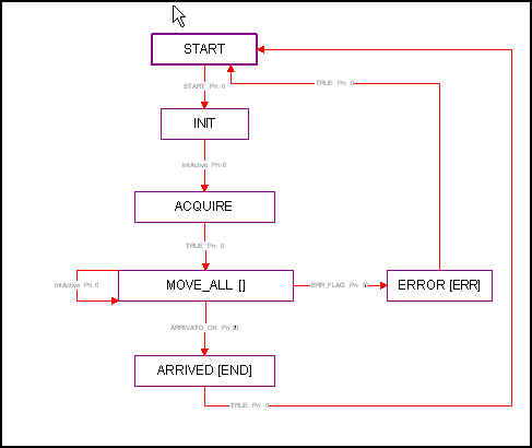
In this way, the following operations are performed: the robot waits at its stand-by position until the user sends the start event (Wait_Ev). Once the start event is received the SMART-3S robot moves from the stand-by position to the position of the target object (Transport), at this point the end-effector is correctly placed (Calibrate), in order to catch the object (Grasp) on the floor; then the object is brought by the manipulator to the desired final position (Transport), the end-effector is correctly positioned (Calibrate), and the object is released (Release); finally, the robot turns back to its stand-by position (Stow). During the setup phase, the user must specify the initial coordinates of the object and its final destination. All trajectories are generated using trapezoidal speed profile. Each one of the mentioned tasks is decomposed into actions. For example, the task Transport is decomposed into the Executing Control Chart (ECC) shown in fig. 3 that is an state-transition diagram that explain the internal beahviour of each task.The Transport FB is decomposed in the follow actions : INIT to performs some initialization of FB parameter, ACQUIRE to get actual robot position, MOVE_ALL that control each link of the robot from actual position to desiderd position, specified by user. Finally ARRIVED state generate an END event to signal to other FBs that robot has reach the desidered position. This action can be reused in other task or specified by composite FB.
Once the FRM has been completed by the control system designer, the ARM is defined by the software/hardware designer, as discussed in section 6. In this way, the architectural model for both low-level and high-level control system parts is defined. Furthermore, a model for the robot has been designed in order to perform the closed-loop simulation. Thus, three application modules have been defined for the considered system. The first describes the C3G controller (low-level control), the second represents the 486 PC (high-level control), and the third realises a dynamic model of the robot (controlled system). The first two application modules define the application implementing the mission ACQUIRE_SAMPLE.

Fig. 3 - Transport Executing Control Chart
The controller application module is composed of two parts. The first generates an interrupt signal every 10 ms, which is detected by the supervisor PC and read and writes the shared memory for the communication with the supervisor PC. The second part of the controller controls the robot links by executing a PID algorithm with a sampling time equal to 1 ms, reading the actual links positions.
The PC application module reads the robot joint position and other relevant variables and writes the position setpoints for each robot link in a shared memory. After about 8 ms the C3G controller reads the position setpoints, and writes the shared memory.
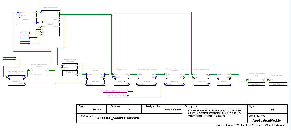
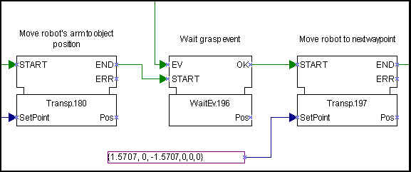
The PC application module implements the supervisor of the whole mission. Basically, it is composed according to the automaton illustrated in Fig. 2, where each task is translated into an ECC (fig. 3) or composite FB. The task synchronisation is realised through the event connection. The EV input event represents the start of the experiment provided by the user, and the START input event represents the termination of the startup and initialisation phases. The meaning of the input and output event of the remaining FBs is evident. As for discrete-time data, in Buffer and BufOut are temporary work variables, Qf is the desired final joint position for the considered task, while Qi is the actual final joint position. The whole PC supervisor application is depicted in Fig 4. The Grasp task has been substituted with a Wait_Ev task since the grippers were not available at the test time. In Fig. 5 is a particular of PC application module.

Fig. 4 - The complete PC application module

Fig. 5 - Transport and Wait_Event FBs used in PC application module
Finally, the Robot application is composed of one application module, and implements the discretized non-linear model of the robot, with a fixed integration step equal to 1 ms.
Once the applications have been defined, and properly associated to the configured devices, the global system behaviour has been simulated (with the automatic generation of simulation code). The event sequences within each application module have thus been investigated, and the planned trajectories have been analysed with classical bidimensional temporal curves and with a graphical 3D animation tool. In this way, the PID algorithm has been tuned, the trajectories accurately calibrated, and the overall control system performances have been optimised.
Finally, the C++ source code for the 486 PC has been generated, cross-compiled on the CAD station, and used to execute the mission on the real system.
Example of code generated for PC application module
![]()
![]() Back to Index ---- Last update : 22 Jan 1998 ---- Creator : Roberto
Fabbri
Back to Index ---- Last update : 22 Jan 1998 ---- Creator : Roberto
Fabbri